- PCD Tools For Wood
- Replaceable Insert Router Bits
- CNC End Mill
- Cutter Head
- Woodworking Tools
- Industries Knives
- Carbide Burr
- Carbide Rotary Burr
- Tungsten Carbide Burr Bits
- Tungsten Carbide Burr Set
- Cylindrical Carbide Burr
- Long Shank Carbide Burr
- Double Cut Carbide Burr
- Flame Carbide Burr
- Cone Carbide Burr
- Burr Blanks
- Carbide Rods
- Tire Reamer Bit
- Tungsten Carbide End Mill
- Carbide Tire Studs
- Snow Tire Studs
- ATV Tire Studs
- Motorcycle Tire Studs
- Mining & Oiling




Design and Construction
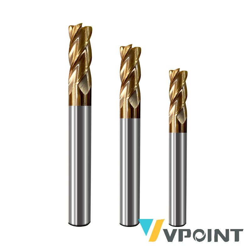
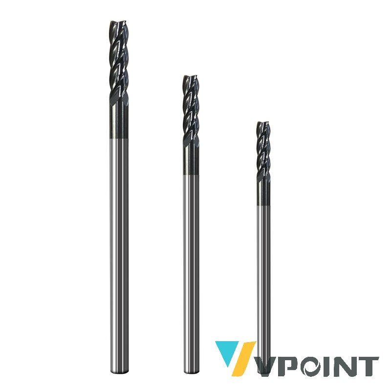
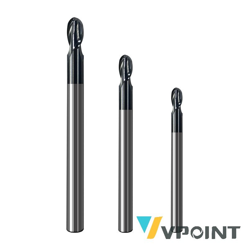
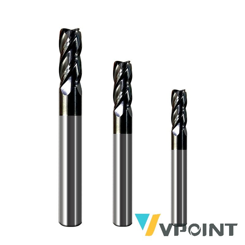
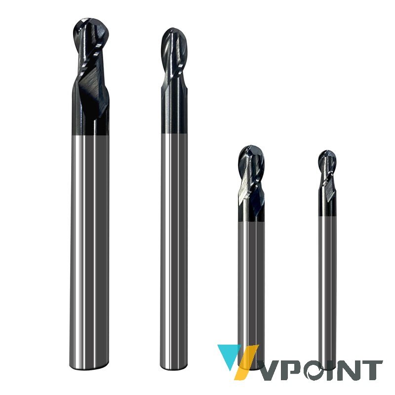
A solid carbide end mill for precision slotting and edge profile work. End geometry is offered in the common forms used on component edges, so the profile is generated by the tool rather than by a long series of stepovers.
How It Works
A square end leaves a sharp corner; a corner-radius end distributes stress and resists chipping; a ball nose generates a true 3D contour. Choosing end geometry at the programming stage saves finishing time on edges and reduces the notch effect at sharp internal corners.
Applications
Component slotting, edge profiling, chamfer and radius features, pocket corner work, 3D contour roughing.
Field Cases
- Component supplier: corner-radius tools stopped the chipping seen at sharp pocket corners.
- Precision shop: edge profiles generated in one programmed pass instead of many stepovers.
- Prototype cell: ball-nose passes produced a smooth 3D contour on a fixture surface.
Performance Data
| Metric | Value / Observation |
|---|---|
| Construction | Solid carbide |
| Primary duty | Precision slotting + edge profiling |
| Geometry choice | Square / corner radius / ball nose |
| Benefit | Profile from the tool, not from stepovers |
Suitable Materials
Carbon and alloy steel, stainless steel, cast iron, aluminium and non-ferrous alloys.
Material Comparison: Square End vs Corner Radius vs Ball Nose on Edges
End geometry selection for edge and contour features. Typical industry practice:
| Factor | Square End | Corner Radius | Ball Nose |
|---|---|---|---|
| Corner produced | Sharp 90-degree | Radiused internal corner | Full radius / 3D |
| Stress at the corner | Concentrated | Distributed | Distributed |
| Chipping tendency | Highest | Lower | Low |
| 3D contour ability | None | Limited | Best |
| Pocket floor | Flat | Flat with radius | Scalloped |
| Typical use | Square pockets, slots | Pocket corners, dies | 3D surfaces, fillets |
Delivery Scope
Single end mill; end geometry and diameter confirmed with the order.
Why Choose VPOINT
End geometry is treated as a design decision, not an afterthought in the toolpath.
Precision & Quality Control
Edge geometry, corner radius and shank runout verified per lot with ISO 9001 batch traceability.
Specifications
Published specification:
| Item | Specification |
|---|---|
| Type | Precision slotting end mill |
| Material | Solid carbide |
| Geometry | Square / corner radius / ball nose |
| Duty | Slotting, edge profiling |
| Workpiece | Steel, stainless, cast iron, aluminium |
| Inspection | Per-lot edge geometry check |
Frequently Asked Questions
Which end geometry should I use?
Square for sharp slots, corner radius for chipping-prone pocket corners, ball nose for 3D contours.
Why do sharp corners chip?
Stress concentrates at the 90-degree corner; a radius distributes it.
Can a ball nose leave a flat floor?
No – it leaves a scalloped surface. Use a square or corner-radius end for flat floors.
Which materials?
Steel, stainless, cast iron, aluminium and non-ferrous alloys.
Is the radius verified?
Yes, edge geometry and corner radius are checked per lot.
Related Search Terms
precision slotting end mill, edge profiling carbide cutter, corner radius end mill, ball nose vs square end, solid carbide slot tool, component edge milling, pocket corner radius tool, 3D contour roughing mill, chipping resistant end mill, CNC edge profile cutter, square end slot mill, radius end mill steel, profiling end mill carbide, sharp corner milling, slot and edge tool