
- PCD Tools For Wood
- Replaceable Insert Router Bits
- CNC End Mill
- Cutter Head
- Woodworking Tools
- Industries Knives
- Carbide Burr
- Carbide Rotary Burr
- Tungsten Carbide Burr Bits
- Tungsten Carbide Burr Set
- Cylindrical Carbide Burr
- Long Shank Carbide Burr
- Double Cut Carbide Burr
- Flame Carbide Burr
- Cone Carbide Burr
- Burr Blanks
- Carbide Rods
- Tire Reamer Bit
- Tungsten Carbide End Mill
- Carbide Tire Studs
- Snow Tire Studs
- ATV Tire Studs
- Motorcycle Tire Studs
- Mining & Oiling
Aluminum Cutting Circular Saw Blade For Radiator: Applications, Materials and Selection Notes

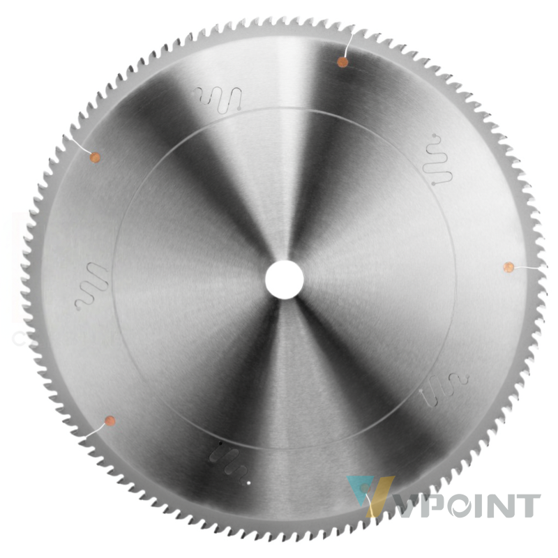
Where the cut usually fails. In a metal shop the failure usually shows up late: the first cut is square, the twentieth is tapered, or teeth strip the moment the tool enters tube.
View Aluminum Cutting Circular Saw Blade For Radiator →
What actually went wrong
Feed per tooth, clamping and coolant set that outcome far more than the tool alone. Running too fast for the alloy work-hardens stainless; running too light lets the edge rub, and a rubbing edge dulls faster than a cutting one.
How Aluminum Cutting Circular Saw Blade For Radiator addresses this problem
A tool with the right grade, pitch and coolant keeps the chip load inside its window along the whole bar, and can be resharpened instead of replaced. Radiator sections are thin-wall extrusion that burrs if the tooth drags: the shear-angle carbide geometry parts the metal cleanly and keeps the section square at the exit. Higher tooth counts keep burr-free ends on thin wall.
Why this matters for a buyer: Brittle laminated faces and veneered plywood chip at the exit, upcut geometry lifts the top veneer, and resin build-up plus a dull tooth leave burn marks. A panel that looks good at the start of a shift fails inspection at the end.
Capability and specifications
The aluminum cutting circular saw blade for radiator production carries carbide teeth ground for thin-wall aluminum. Blades are produced to order: diameter, kerf, bore and tooth count are matched to the radiator cutting machine when ordering.
Which machines this tool is built for
Machine choice changes the result more than most operators expect. The same tool on a rigid spindle with a power feed behaves differently from the same tool fed by hand: chip load, heat and finish all shift. The table below states where this tool is the right choice, what it actually delivers there, and where it should not be used.
| Machine | Fit | What you get | Key limit |
|---|---|---|---|
| Panel saw / beam saw | Recommended | The design case: a rigid arbor, clean flange and scoring or non-scoring geometry give a clean top and bottom edge on coated board. | Flange condition and blade projection control the chip-free result. |
| Sliding table saw | Recommended | A stable carriage and repeatable scoring make it the practical choice for small shops cutting laminated panels. | The carriage must be aligned; a worn slot shows as a step in the edge. |
| Table saw | Workable with limits | Good for solid wood and uncoated plywood with the right tooth count. Coated board needs a scoring pass or a zero-clearance insert. | Riving knife and guard stay fitted; blade height affects chipping. |
| Vertical panel saw | Workable with limits | Good for sizing full sheets where floor space is limited; quality depends on the guide and the support grid. | The sheet must be fully supported; a sagging panel pinches the blade. |
| CNC router | Not recommended | A router spindle cannot take a circular saw blade. | Use a beam saw or a panel saw for blade work. |
Machine by machine: what to expect
Panel saw / beam saw. The design case: a rigid arbor, clean flange and scoring or non-scoring geometry give a clean top and bottom edge on coated board. Flange condition and blade projection control the chip-free result.
Sliding table saw. A stable carriage and repeatable scoring make it the practical choice for small shops cutting laminated panels. The carriage must be aligned; a worn slot shows as a step in the edge.
Table saw. Good for solid wood and uncoated plywood with the right tooth count. Coated board needs a scoring pass or a zero-clearance insert. Riving knife and guard stay fitted; blade height affects chipping.
In short: if the work is repetitive and the machine is rigid, this tool is at its best. If the setup relies on hand control, expect the finish to depend on feed discipline rather than on the tool alone.
Typical production applications
- Sizing melamine-faced and HPL-faced panels with a clean top and bottom edge.
- Cross-cutting solid wood and glued panels to length.
- Trimming veneered plywood and MDF door blanks.
- Cutting aluminium and non-ferrous profiles with the correct tooth geometry.
Each of these is a repeated operation, which is where consistency matters more than a single good test cut: the first part and the five-hundredth part have to match.
Installation, step by step
- Isolate the power and lock the spindle. Disconnect the machine and engage the spindle lock before removing or fitting a blade or cutterhead.
- Clean the flange, collar and bore. Dust or resin between the flange and the body tilts the tool. A tilted blade cuts a stepped edge and puts bending stress into the plate.
- Check the bore and drive pins. The bore must match the arbor, and any drive pin or keyway must seat fully. Never pack a loose bore with tape or shim stock.
- Fit the correct rotation direction. The arrow on the body must match the machine rotation. A reversed blade or head does not cut, and can be thrown.
- Torque evenly, in a cross pattern for insert heads. Tighten insert screws diagonally to the toolmaker torque, with clean seats and new screws where specified. Uneven torque distorts the seat and can crack the body.
- Set position and check clearance. Set blade projection or cutterhead position, rotate the spindle by hand through a full turn, and confirm nothing fouls the guard, fence or table insert.
- Run in free air, then take a test cut. Listen for a new noise and check for vibration before the first workpiece. A test cut in scrap of the same material confirms height, fence and finish.
Two rules cover most of the risk: the shank or bore must be clean, and the tool must be seated with enough engagement. Everything else, torque, projection, guard clearance, is a check on those two.
Installation mistakes that cause most failures
- Dirty flange or collar The body sits at an angle, the cut edge steps, and the plate carries a bending load it was not designed for.
- Reversed rotation The tool rubs instead of cutting, heat rises fast, and the workpiece can be kicked back.
- Uneven or excessive screw torque Cracks the body or distorts insert seats. Use a torque wrench and a cross pattern.
- Worn bore or a missing bushing Shows up as wobble, noise and a poor finish, and accelerates bore wear on the arbor.
- A blade run above its rated speed The most dangerous mistake on a saw: the plate can distort or fail. Check the marking on the body.
- Re-using insert screws Worn heads and stretched shanks lose preload. Replace screws at the interval the toolmaker specifies.
- Guards or riving knife removed for convenience Removes the protection that makes a kickback survivable. Refit them before the next cut.
Rules during the cut
- Let the machine reach full speed before the work enters the cut.
- Keep the workpiece against the fence or reference face throughout the pass; a lift at the end is where most chipping happens.
- Use push sticks or a power feed. Hands never enter the line of the cut.
- Match feed per tooth to the material. Too light a chip load polishes the edge, too heavy a load overloads the arbor.
- Keep the guard, riving knife and brake in place and working.
- Check the first part of every batch. A change in edge quality is the earliest warning of a worn or damaged edge.
- Shut down and lock out before clearing chips from the cutting zone.
Maintenance and inspection schedule
| Interval | What to do |
|---|---|
| Every shift | Wipe resin from the flutes and the shank with solvent and a soft brush. Inspect the cutting edges under a light for chipping, a bright wear land or blue heat marks. Check that the collet or flange is clean before mounting. |
| Weekly | Check runout with a dial indicator against the toolmaker limit. Inspect the collet for scoring or ovality and replace it if marked. On bearing-guided tools, check the bearing for wobble and free rotation. Verify extraction airflow at the hood. |
| Monthly | Review the tool log by tool number: metres cut, material, and any change in finish or feed force. Send the tool for resharpening when finish drops or feed force rises, not on a calendar date. Replace worn collets and damaged screws as consumables. |
Inspect with a 10x magnifier in good light. What to look for: a chipped or flaked corner, a bright wear land running back from the edge, cracks at the joint between carbide and steel body, blue or straw discolouration from heat, and resin filling the flute. On a mounted tool, a dial indicator on the shank or body shows runout, and a test cut in scrap shows the result that matters.
When to stop using a tool: any visible crack, a chipped cutting corner, a bent shank or a body that has been run hot is a removal, not a touch-up. A tool that has lost its edge can be resharpened; a tool with a crack cannot be made safe.
Why tools break, chip or deform
Nearly every failure has a setup cause rather than a manufacturing cause. The table maps the symptom an operator sees to the mechanism behind it and the correction that actually removes the cause.
| Symptom | Most likely cause | Correction |
|---|---|---|
| Cracked plate or body | Dirty flange, uneven nut torque, or a blade run above its rated speed. | Clean flanges, torque to spec, and check the speed marking on the body. |
| Chipped teeth or inserts | Impact with fasteners, hard inclusions or a jammed workpiece. | Inspect material, use metal detection, and never force a stalled cut. |
| Insert screws loosen in service | Re-used screws, wrong torque, or dirty seats. | Fit new screws, torque in a cross pattern, and clean the seats before assembly. |
| Bore wear and wobble | Arbor runout, wrong bore tolerance, or a missing bushing. | Check arbor runout, fit the correct bushing, and replace a worn body rather than shimming it. |
| Burn marks along the cut | Feed too slow, dull edge, or resin on the body. | Raise feed, clean the tool, and resharpen or rotate the edge. |
| Cutting circle changed after service | The tool was reground without re-datuming the machine. | Re-set the machine datum after service and keep a matched spare set for critical profiles. |
| Noise and impact on entry | Too many teeth or knives engaging at once, or a straight-knife geometry. | Use staggered or helical geometry, reduce feed per tooth, and check spindle condition. |
Where it wins, and where it does not
Advantages: Radiator production lines Thin-wall aluminum cutting Extrusion section cutting Heat-sink and radiator fabrication
Limitations, stated honestly: Plywood, MDF, chipboard, laminated panels, solid wood and, with the right tooth geometry, non-ferrous profiles. Not for steel, masonry or panels with embedded metal.
Machining characteristics and performance
Cutting data for metal is set by the tool grade and the machine, not by a woodworking chart. Start from the supplier chart for the alloy and its hardness, hold the chip load per tooth constant, and confirm coolant flow or air blast before a long run.
All published parameter values are standard reference values for guidance only. Confirm them against your tool, spindle and workpiece before a production run.
Compared with the alternative
Compared with a general-purpose blade, a dedicated geometry scores brittle face veneers before the main chip; PCD adds abrasion resistance where carbide would need frequent changes.
From the product comparison section: Radiator sections are thin steel or aluminium sections cut to length. The saw runs at the edge of the material, so chip control and a stable tooth are what matter. Property | Solid Carbide Integrated Arc Bit (This Tool) | Replaceable-Insert Spiral Bit | Tooth material | Tungsten carbide teeth brazed onto a steel body (TCT) | Polycrystalline diamond teeth (PCD) | Tooth form | Variable tooth count (…
Materials and machine fit
Materials it cuts: Aluminum alloys and extrusion Radiator sections Thin-wall aluminum profiles Non-ferrous metals The shear-angle carbide geometry cuts thin-wall aluminum without dragging or burring the exit.
Plywood, MDF, chipboard, laminated panels, solid wood and, with the right tooth geometry, non-ferrous profiles. Not for steel, masonry or panels with embedded metal.
Machine fit: Panel saws, sliding table saws, beam saws and table saws with a matching bore and flange. Not for a router spindle or a portable die grinder.
Frequently asked questions
More teeth give a cleaner edge on thin or faced panels; fewer teeth clear chips faster on thick stock.
The answer depends on the workpiece and the machine setup. The specification table on the product page is the starting point, and our engineers can confirm it against your machine on WhatsApp.
Set by diameter and tooth count — larger diameters run slower; start near 4,500–6,000 rpm for panel work.
Use the parameter table as a reference and verify on a test cut before a production batch.
Can I run this on a router spindle?
No. A bore-mounted tool needs an arbor, a flange and a guard; the machine table above shows the machines it is designed for.
How do I know the flange is clean enough?
Wipe it with solvent and look for a bright, even surface with no resin ring. Any raised spot tilts the tool and shows up as a stepped cut edge.
Why did the body crack?
Almost always uneven torque on a dirty flange, or a tool run above its rated speed. Both put a bending load into the body that it cannot survive.
How often should it be sharpened?
By symptom, not by calendar: when surface finish drops, feed force rises, or the chips turn to dust. Send the tool for service with its tool number so the log stays usable.
Sources and standards
Amana Tool. "Knowledge Base: shank concentricity, collet installation, vibration and sharpening." www.amanatool.com/knowledge_base. Accessed 10 Nov. 2026.
Amana Tool. "Safety Guidelines for Router Bits and Saw Blades." www.amanatool.com/safety. Accessed 10 Nov. 2026.
C.M.T. Utensili. Router bit instruction sheet: collet seating, feed rate and maintenance guidance. Accessed 10 Nov. 2026.
Standards: ISO 9001 · UNSPSC · eClass
Full specifications for Aluminum Cutting Circular Saw Blade For Radiator · Resources hub · Ask a VPOINT engineer on WhatsApp →